Launching the wood calculator first requires you to accept the disclaimer that confirms you understand the limitations of the software.
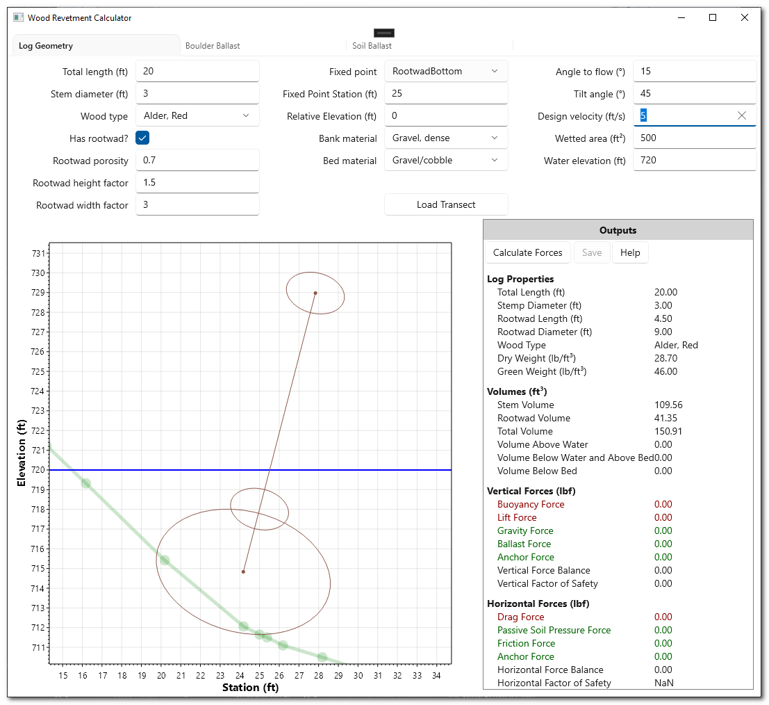
The main window is divided into three main sections:
- Inputs
- Visualization
- Outputs
Getting Started
- Launch the Wood Calculator software.
- Click the Load Reference Line button and browse to a HEC RAS plan file. This must be a file with the name
*.p??.hdfwhere??refers to the plan number. There must also be a corresponding plan file with the same name but without the.hdffile extension. The software reads this file to determine the geometry file name by reading theGeom Fileentry in this text file. - If the geoemtry file contains multiple reference lines, a dialog will appear offering to select which reference line that you want to use as the transect for the log calculator.
- Adjust the log, soil and and water inputs as desired.
- Click Calculate Forces to update the forces associated with the current scenario.
Reference Lines
If the specified HDF geometry file contains multiple reference lines a dialog appears to select which reference line should be used as the river cross section.
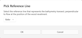
The reference line should always be perpendicular to flow. The calculations assume a uniform channel with the same cross sectional profile.
Inputs
The inputs require you to define the log dimensions, it’s position and orientation relative to a river transect that is perpendicular to flow, as well as the flow velocity itself.
It’s important to note that the transect is always considered perpendicular to flow. The force calculations project the area of the log onto the transect plane.
Total Length
This is the total length of the tree stem (ft), including rootwad if one is defined.
Stem Diameter
This is the diameter of the tip of the log tree stem. The log is assumed to be a cylinder and so this diameter applies to the entire log down to either the base of the log if there is no rootwad, or the top of the rootwad if there is one.
Wood Type
Pick one of the wood types from the dropdown list. The specific green and dry weights used are taken from Rafferty (2016) and are displayed in the Outputs section of the main window.
Rootwad
Include or exclude a rootwad using the checkbox. The dimensions of the rootwad are defined in terms of multiples of the log stem diameter. The rootwad porosity refers to the proportion of the rootwad that is considered air or wood roots. A porosity of 1 assumes that the log is 100% solid roots. A porosity of 0 assumes that the rootwad is 100% air.
Fixed Point
A fixed point along the transect is used to position the log. pick between one of the three types:
- Rootwad bottom - the underside of the based of the tree stem.
- Stem tip bottom - the underside of the tip of the tree stem.
- Rootwad collar bottom - the underside of the top of the rootwad, if there is one. If there is no rootwad defined then this option is the same as the rootwad bottom.
The location of this fixed point is defined by a distance along the transect and then offset by the specified elevation.
Soils
Select the appropriate type of material for the bank and bed. The corresponding properties are displayed in the Outputs section.
Orientation
The angle to flow (azimuth) is measured from the transect orientation. An angle to flow of zero refers to parrallel to the transect. 90 degrees refers to the stem tip upstream and the base downstream.
The tilt angle is relative to horizontal. A tilt angle of zero refers to a horizontal log. 90 degrees refers to a log with the tip on the ground and the base in the air.
Velocity
The design velocity for the wood revetment is specified in feet per second.
Wetted Area
The cross sectional wetted area is required because it cannot be assumed that the transect spans the entire channel. The specified value should represent the cross sectional area of the channel that corresponds with the design velocity.
Water Elevation
The water elevation is defined in abolsute terms in the same datum as the transect coordinates.
Boulders
The boulder ballast tab allows for the specification of additional weight on top of the log. All boulders are considered to be placed directly on top of the log (deadman anchors are not permitted) and are considered 100% in flow for the purposes of horizontal drag forces.
Visualization
The visualization shows the log, water surface and transect in a cartesian plot. The x axis reflects horizontal stationing along the transect. The y axis reflects vertical elevations using the same datum as the HEC geometry file.
Outputs
Outputs are divided into four sections summarizing the log properties, soil properties, log volumes, vertical and horizontal forces. The Log and soil properties automatically reflect any changes in the inputs. The remaining categories require the forces to be calculated before they reflect values.
The outputs can be saved to JSON or CSV text file format.